This post is also available as PDF document for download.
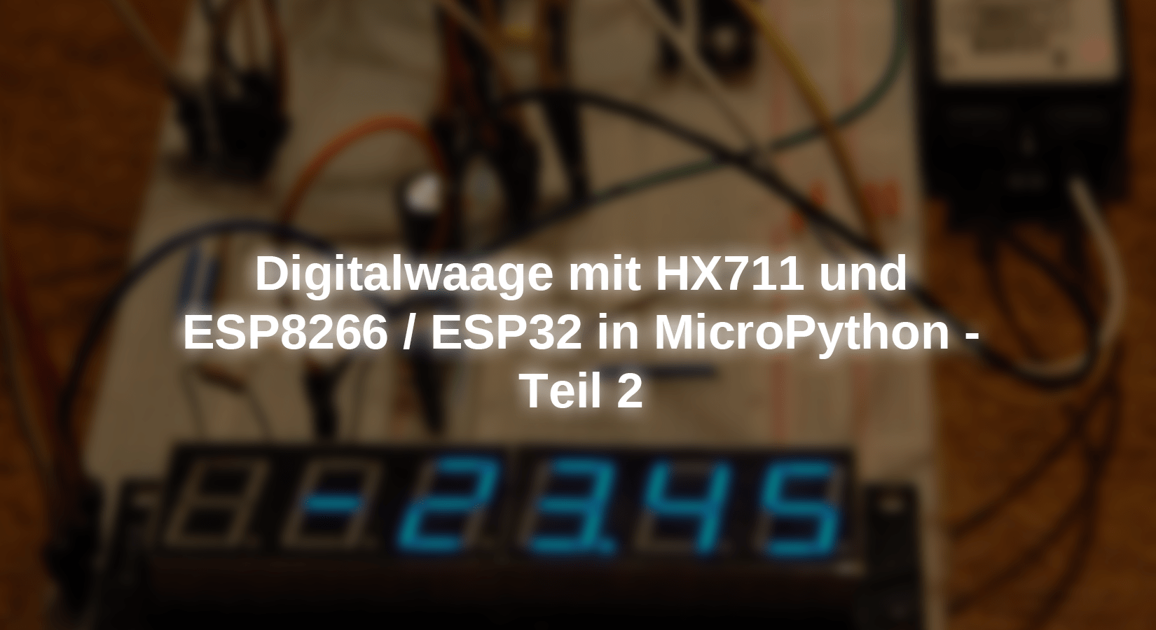
LCD and OLED displays are nice. Some information can be displayed on the 2, 3 or 6 lines. OLEDs are even graphics. But sometimes I want an ad with really big digits. With my little ones Self-made scales as in part 1 With 100g and 1000g I used OLED displays. Now there was a 20kg copy and there I found the 0.96 "ad, but also a usual 1602 LCD too popy.
When searching online, I came across a 6-fold LED display with 14mm high digits. That was exactly what I needed, especially since the control is only done via two lines. With the help of the data sheet, it quickly became clear that the transmission protocol corresponds almost exactly to the I2C protocol, but not quite. The only deviation: no hardware address is sent at the beginning of the transfer. But otherwise there is a start condition, a stop condition and a acknowledge bit, as with the I2C bus.
Of course, the I2C module, which is built into the core of Micropython, cannot be used by these circumstances. So I knitted a replacement module based on the data sheet, which optimally meets the conditions for the scale display. The display still had a surprise in stock. But more about that later. In this episode of
Micropython on the ESP32 and ESP8266
today
Digital scale with LED display
First of all, we take care of the hardware of the display. In addition to this, nothing more is required for the scale in addition to the previous assemblies. The driver module for the seven-segment ads sits on the underside of the module.

Figure 1: TM1637 from above

Figure 2: TM1637 from below
The previous around the ADC for the scale, a HX711 module and a Controller of Type ESP8266 or ESP32, as well as a button to take into account the Tara. You can find out in the first how the controller works with the driver module Post on the subject of scales. Here we will examine the module for the new display and adapt the scales to the new display.
Hardware
|
1 |
D1 Mini Nodemcu with ESP8266-12F WLAN module or D1 Mini V3 Nodemcu with ESP8266-12F or Nodemcu Lua Amica Module V2 ESP8266 ESP-12F WiFi or Nodemcu Lua Lolin V3 Module ESP8266 ESP-12F WIFI or ESP32 Dev Kit C V4 unplacerated or |
|
1 |
TM1637 6 Digit Blue LED display 7 segment display module with 0.56 inches |
|
1 |
Weighing cell 20 kg |
|
1 |
HX711 AD converter for weighing cells |
|
1 |
|
|
various |
Jumper Wire cable 3 x 40 pcs. 20 cm M2M / F2M / F2F each possibly too |
|
optional |
The Logic Analyzer is a very useful instrument if it is hooked when it comes to serial data transmission. In many cases, it replaces an expensive DSO (digital memory oscilloscope) and also offers the advantage of longer recordings, into which you can then zoom in. There is one for the device linked here Free operating software, the part is controlled via the PC. It helped me in many desperate cases, also in this case. The protocol of the TM1637 is sufficiently shown in the data sheet, but you are happy to overlook a detail. If you then compare the pulse diagram in the data sheet with what you have created yourself, you get to solving the problem very quickly.
Here are the circuits for ESP32 and ESP8266:

Figure 3: Libra - circuit for ESP32 and ESP8266

Figure 4: Display structure with TM1637 in the test with the ESP8266 D1 mini
The software
For flashing and the programming of the ESP32:
Thonny or
Used firmware for the ESP32:
Used firmware for the ESP8266:
The micropython programs for the project:
HX711NEU.PY API for the AX711
scale1637.py The operating program
tm1637.py API for the 7-segment display
Micropython - Language - Modules and Programs
To install Thonny you will find one here Detailed instructions (English version). There is also a description of how that Micropython firmware (As of 18.06.2022) on the ESP chip burned becomes.
Micropython is an interpreter language. The main difference to the Arduino IDE, where you always flash entire programs, is that you only have to flash the Micropython firmware once on the ESP32 so that the controller understands micropython instructions. You can use Thonny, µpycraft or ESPTOOL.PY. For Thonny I have the process here described.
As soon as the firmware has flashed, you can easily talk to your controller in a dialogue, test individual commands and see the answer immediately without having to compile and transmit an entire program beforehand. That is exactly what bothers me on the Arduino IDE. You simply save an enormous time if you can check simple tests of the syntax and hardware to trying out and refining functions and entire program parts via the command line before knitting a program from it. For this purpose, I always like to create small test programs. As a kind of macro, they summarize recurring commands. Whole applications then develop from such program fragments.
Autostart
If the program is to start autonomously by switching on the controller, copy the program text into a newly created blank tile. Save this file under boot.py in WorkSpace and upload it to the ESP chip. The program starts automatically the next time the reset or switching on.
Test programs
Programs from the current editor window in the Thonny-IDE are started manually via the F5 button. This can be done faster than the mouse click on the start button, or via the menu run. Only the modules used in the program must be in the flash of the ESP32.
In between, Arduino id again?
Should you later use the controller together with the Arduino IDE, just flash the program in the usual way. However, the ESP32/ESP8266 then forgot that it has ever spoken Micropython. Conversely, any espressif chip that contains a compiled program from the Arduino IDE or AT-Firmware or Lua or ... can be easily provided with the micropython firmware. The process is always like here described.
The class TM1637
The TM1637 does not use a hardware address, as is usually the case on the I2C bus, I mentioned that above. There are also no registers, but only commands, commands, namely three: Data Command, Display and Control Command and Address Command. The signal sequence in the following figure represents writing access with automatic counting up the address after each data byte sent.
The sequence begins with a start-up condition, Dio goes to low while CLK is on high.

Figure 5: Signal course when writing in the SRAM of the TM1637
With the falling clock flank, the controller places the first database on the dio line and then relies on High, the TM1637 takes over the bit. The first byte is the data command, 0x40. If 8 bits, starting at the LSB (Least Significant bit = low -quality bit), are transferred, the TM1637 pulls dio to low when the transmission was ok. The ninth rising clock flank triggers the Acknowledge-bit. A stop condition follows (CLK is high, Dio follows up after a delay) and immediately afterwards a new start condition.
With the Address Command 0xc0, the controller then sends the first memory address from which the data is continued. After each data byte there is a Acknowledge and a stop condition after the last byte.
The third command, with its own start-Condition, Acknowledge and Stop Condition, controls the display. The lower three bits set the brightness, Bit 3 switches on or off.
Let's take a look at how everything can be implemented in terms of program. We start with a low import volume.
 From machine import Pin code
 From time import Sleep_us, Sleep_ms
A few exception classes for error treatment follow. The container class Tm1637_error inherit from Exception, the mother of all exception. The subclasses of Tm1637_error.
class Tm1637_error(Exception):
passport
class Brightnesserror(Tm1637_error):
def __init__(self):
Excellent().__init__("Wrong contrast value",
"0 <= value <= 7")
class Position terror(Tm1637_error):
def __init__(self):
Excellent().__init__("Wrong position value",
"0 <= value <= 5")
class Stringlengherror(Tm1637_error):
def __init__(self):
Excellent().__init__("String too long",
"0 <= value <= 5")
The TM1637 class is declared. The constants set the underlying values for the commands. MSB serves to activate the decimal point of a digit by the segment code ornamented becomes.
 class TM1637():
     Datacmd = const(0x40)  # Data CMD - Write, Auto -Incr., Normal
     ADRCMD = const(0xc0) # Address Command f. Register 0
     Dispatcher = const(0x80) # DISP CTRL CMD - on/from contrast
     Overdraft = const(0x08) # display on
     MSB = const(0x80)  # Decimal point
     A=[2,1,0,5,4,3]
     Segm=bytearar(b '\ x3f \ x06 \ x5b \ x4f \ x66 \ x6d \ x7d \ x07 \ x7f \ x6f')
To the variables, the list A and the bytearar Segm I have to go out something.
To my astonishment, the sequence of the digits in the display was not from left to right, or the other way round, but as in Figure 3. The matter complicates the matter a little.

Figure 6: Display arrangement
If I form an display ring from a measured value, the digits cannot be sent to the display in their natural order because it creates a small mess. From 123456 would 321654, sometimes something else! The list a = [2.1.0.5.4.3] Make the assignment between the string and the real display position. What is in position 0 in the string must be written in the memory for the second digit so that the number appears in the display on the far left. The 1 must land in Digit 2. The index of the list is therefore the position in the digit string, the list element, the digit number, where the number, or better, whose segment pattern is supposed to land. I'll come back to it later.
The bytearar Segm Contains the segment patterns of the digits 0 to 9 according to the scheme in Figure 5.

Figure 7: segment arrangement
Each segment corresponds to a bit position according to the following pattern.

Figure 8: Dib coding
If we write 0x6d in the display storage 3, a 5 appears in the position on the right on the outside on the display and if we start with the address 0xC0, then 0x6d must be transmitted as fourth to land in 0xc3.
It continues with the constructor of the class TM1637, the method __init__().
     def __init__(self, CLK=Pin code(5), dio=Pin code(4), Brightness=3):
         self.CLK = CLK
         self.dio = dio
         IF need 0 <= Brightness <= 7:
             raise Brightnesserror
         self.Brightness = Brightness
         self.CLK.init(Pin code.OUT, value=1)
         self.dio.init(Pin code.OUT, value=1)
         self.delay=5
         Sleep_us(10) # 10Us wait
         self.Clear display()
         print("TM1637 Ready")
Three optional keyword parameters can be handed over, the PIN objects for CLK and DIO, as well as for contrast or the brightness as they want. If no argument is handed over, the default values apply. All parameters are assigned attributes, the contrast value is checked via this for compliance with the value range. Lies Brightness not in the permissible area, then one Brightnesserror-Sexception thrown.
The pins are set to exit. As a delay for the clock, I present 5µs, which corresponds to a frequency of 100kHz. We wait briefly, delete the display, then the constructor reports the operational readiness of the object in the terminal.
With latency() we can do the integer argument in Val As the value of the delay in the attribute delay Layer after the value range (1… 20 for 500kHz ... 50kHz) was limited if necessary. Called without an argument, the method provides the current value of delay back.
     def latency(self, Val=None):
         IF Val is None:
             return self.delay
         Else:
             IF type (Val) != intimately:
                 raise Latency
             Val = min(Max(Val,1),20)
             self.delay=Val
             return Val
The method start -on() follows the above requirements for the signal sequence. The idle state on both lines is high. Dio Go to low first, then follows CLK.
    def start -on(self):
        self.dio(0)
        Sleep_us(self.delay)
        self.CLK(0)
        Sleep_us(self.delay)
To create a stop condition, Dio must first be safe on low and the clock line at high. Delayed then goes to high.
    def stopcond(self):
        self.dio(0)
        Sleep_us(self.delay)
        self.CLK(1)
        Sleep_us(self.delay)
        self.dio(1)
The transfer of the data command bytes is embedded between the start and stop condition.
   def Writedatacmd(self):
        self.start -on()
        self.writebyte(Datacmd)
        self.stopcond()
The same applies to Writedispcntrl(). However, more bits are carried out on the bare commandobyte 0x80 Ornament gripped on. With Overdraft = 0x08 we set Bit 3. The three contrast bits 2: 0 are in Brightness.
   def Writedispcntrl(self):
        self.start -on()
        self.writebyte(Dispatcher | Overdraft | self.Brightness)
        self.stopcond()
writebyte() is the universal method for sending a byte taking into account the Acknowledge bits, which is not scanned. Otherwise we would have to switch to the entrance, read in the condition and then switch back to the output. So far no mistake has occurred, so I left out the exam.
    def writebyte(self, B):
        for I in range(8):
            self.dio((B >> I) & 1)
            Sleep_us(self.delay)
            self.CLK(1)
            Sleep_us(self.delay)
            self.CLK(0)
            Sleep_us(self.delay)
        Sleep_us(self.delay) # ACK clock follows
        self.CLK(1)
        Sleep_us(self.delay)
        self.CLK(0) # Prepare by the naechst Byte
        Sleep_us(self.delay)
The for loop pushes the handed over to the dio line with the LSB. CLK is still on low. The byte is pushed to the right by i = 0 to 7 positions and now the LSB is masked. The result is 0 or 1. The output is controlled.
After the condition is stabilized, we create an increasing flank to CLK, the TM1637 samplates the condition on dio. After the clock is back on low, the next bit follows, the process is repeated until all bits are outside. CLK remains after the last bit for delay Seconds on low, then the last thing is the Acknowledge clock, which ends again with CLK = low. Another byte or a stop condition can now follow.
The method is used to test the display but also for output very specific patterns, for example for ASCII signs segment(). In SEG the pattern is handed over (default 0xff) and in POS The number of the digit (default 0x00). The output position is checked.
    def segment(self,SEG=0xff,POS=0):
        IF need 0 <= POS <= 5:
            raise Position terror
        self.Writedatacmd()
        self.start -on()
        self.writebyte(ADRCMD | TM1637.A[POS])
        self.writebyte(SEG)
        self.stopcond()
        self.Writedispcntrl()
Writedatacmd() has its own start and stop conditions. Before the address is sent, a start-up condition must be installed. The segment description byte, the stop condition and the display control byte follow the basic memory address with Odered Digit number. POS If the real position of the digit speaks in the advertisement, the indicated list element the physical memory address, 0 becomes 2, 5 the 3 etc.
>>> From TM1637 import TM1637
>>> TM=TM1637()
>>> but=bytearar(B '\ X77 \ X7C \ X79 \ X50')
>>> for I in range(len(but)):
        TM.segment(but[I],I)

Figure 9: Letter but
contrast() works similarly to latency(). The current value is returned without an argument. With a value between 0 and 7 including the borders, the brightness is re -set. In connection with a photo resistance, for example, the brightness of the display could be adapted to the ambient light.
    def contrast(self, Val=None):
        IF Val is None:
            return self._brightness
        IF need 0 <= Val <= 7:
            raise Brightnesserror
        self.Brightness = Val
        self.Writedatacmd()
        self.Writedispcntrl()
I send six zero-bytes to delete the display.
    def Clear display(self):
        segment=(bytearar(b '\ x00 \ x00 \ x00 \ x00 \ x00'),-1)
        self.writes(segment)
The tupel segment Contains a bytearar with the segment codes and an integer. This indicates the number of the digit, in which the decimal point must be controlled if the number is the type float acts. The value -1 indicates an integer. We come to talk more about it below. We hand over the tupel writes().
Done a function test of all filaments lump test() according to the same pattern as Clear display().
    def lump test(self):
        segment=(bytearar(B '\ XFF \ XFF \ XFF \ XFF \ XFF \ XFF'),-1)
        self.writes(segment)
Send up to six segment patterns from a given position, which can writes(). The patterns are in the tupel segments, the position comes behind. We carry out plausibility control for this value.
Now we are breaking the tupel into a pattern and decimal point position. The string can only be as long as from POS Digits are still there, we test that.
If everything fits, we send the data command, followed by a start condition and the start address. The for loop brings the digits to the correct position.
    def writes(self, segments, POS=0):
        IF need 0 <= POS <= 5:
            raise Position terror
        S,P=segments
# Print (S, P)
        IF len(S) + POS > 6:
            raise Stringlengherror
        self.Writedatacmd()
        self.start -on()
        self.writebyte(ADRCMD | POS)
        for I in range(POS,6):
            C=S[TM1637.A[I]]
            IF P==TM1637.A[I]:
                C|=MSB
            self.writebyte(C)
        self.stopcond()
        self.Writedispcntrl()
The segment patterns for numbers that we have with Number2 segment() Create all start from the real digit position on the far left. This is the physical position 2 in the memory. However, we have to start the broadcast with the relative memory address 0, absolutely 0xC0, otherwise we would have to send the address to each data byte. However, we want to use the auto-increment and send the six data bytes in a dishes. Here, too, the list helps a = [2.1.0.5.4.3]. She tells us which sign of the string must be sent to which storage point.

Figure 10: assign string to memory
The I The physical storage positions go through in the for loop. It serves as a pointer in the list A. The element at the respective list position is a pointer on the position of the sign in the string or bytearar. The code for this character is written in the storage point that is currently I is addressed.
If P the value of a [i] Has, the MSB is still Odered for the segment code, which means that the decimal point is activated. Then the byte is sent to the TM1637.
After the usually six bytes comes a stop condition and then the display control command.
There is still no coding of integer and flow of flow in segment codes. Number2 segment() takes the number, which, of course, must not be longer than 6 characters with a comma and sign and an optional argument K. With this we state the number of decimal places if the number of float is. We check the first thing first.
    def Number2 segment(self, n, K=1):
        IF type(n)==intimately:
            S="{:>6}".format(n)
        elif type(n)==float:
            S="{:>7."+Str(K)+"f}"
            S=S.format(n)
        Else:
            raise Type
Is the guy intimately, i.e. integrated, then change the value via the format ring into a right -fitting (">") string, with any leading spaces, from the minimal length 6. Is the number of the type float, we have to take into account that the decimal point is eliminated as a separate sign when treating the string. That is why we give the string a minimal width of 7 characters. We work in the format ring the number of decimal places.
        POS=S.find(".")
        IF POS != -1:
            S=S.replac('.','')
            POS-=1
Then we look for the position of a potential decimal point. If nobody exists, then it is a integer POS receives the value -1. Otherwise contains POS the index to the point. In this case, we replace the point in the string with an empty sign. We reduce the position by 1, because the point must be taken into account in the Digit in front of it.
        IF len(S)>6:
            raise Stringlengherror
        segment = bytearar(len(S))
If the prepared string is now longer than 6 characters, we throw one Stringlengherror-Exception. If everything is in the green, we create a bytearar from the length of the string. According to the current situation, it should always have length 6. Now it goes to the actual coding. The for loop rattles off every character.
        for I in range(len(S)):
            IF S[I] == " ":
                segment[I]=0x00
Is the sign in the position I A spaces, no filament may shine - segment code 0x00.
            elif S[I] == "-":
                segment[I]=0x40
If it is a minus sign, then we only need the medium line - Code 0x40
            Else:
                segment[I] = TM1637.Segm[ordained(S[I]) - 48]
        return (segment,POS)
In all other cases we get the code from the bytearar Segm. The number of 48 ASCII code of the number serves as index. 48 is the ASCII code of the "0".
The bytearar is returned together with the point position as a tupel.
The operating program for the scales
By using the LED display, the operating program has become significantly slimmer. This is due to the simpler type of display control. In connection with the scales, I also taught the display a little plain text that it can do "error" and "Tara", not exactly artistically valuable, but sufficient for the purpose. With the effectively 40 program lines, the program is very clear. Ok, the main work is done in the HX711 and TM1637 modules, but even they are still quite cute with 139 or 161 lines. In any case, everything fits very easily into an ESP8266.
From machine import Pin code
From time import sleep
From TM1637 import TM1637
From HX711 new import HX711
We need pins for the GPIO control, sleep for breaks and of course the classes TM1637 and HX711.
A TM1637 object is instantiated and the PIN objects for the operation of the HX711 are generated.
I do not have to specify the PIN objects when calling for the display of the display object because I use an ESP8266 and therefore use the default pins, GPIO5 and GPIO4. The flash button or an external button on GPIO0 serves as the button.
TM=TM1637()
dot=Pin code(14)
dpclk=Pin code(2)
button=Pin code(0,Pin code.IN,Pin code.Pull_up) # D3
There is a single function. Putnumber() does the measuring value edition. The value of the HX711 is in a Segment-Tupel encoded and sent to the display.
def Putnumber(n):
    S=TM.Number2 segment(n)
    TM.writes(S)
The attempt follows to initialize the scale. We hand over the PIN objects for the data and clock management to the constructor. The chip is woken up. We work with channel 1, the weighing cell is located on the input A of the HX711, and we work with full reinforcements. The Tara is automatically determined for every start of the program, with 25 individual measurements. A lamp test provides information about the function of all filaments and that everything has been running without errors so far.
try:
    HX = HX711(dot,dpclk)
    HX.wake up()
    HX.channel(1)
    HX.tara(25)
    TM.lump test()
    sleep(1)
    print("Libra started")
If an error has occurred, the except block "Error" reports on the display and the program will end.
except:
    print("HX711 does not initialize")
    S=(b "\ x79 \ x50 \ x50 \ x5c \ x50 \ x00",-1)
    TM.writes(S)
    sys.exit()
There are two jobs in the main loop. When the button is pressed, a new Tara value is determined and saved. This allows us to withdraw the packaging weight or to weigh ingredients. "Tara" appears in the ad. After the measurement process, the program will only continue to work when the button has been released.
while 1:
    IF button.value() == 0:
        S=(B "\ x00 \ x78 \ x77 \ x50 \ x77 \ x00",-1)
        TM.writes(S)
        HX.tara(25)
        while button.value()==0:
            passport
My 20kg weighing cell provides values that wobble at the tenth of gram. In other words, 0.1 grams is the insecure body. I have therefore hidden them and are satisfied with the fact that the scale measures to 1 gram exactly. That is 0.005% of the maximum value of 20,000 grams. This resolution is really great!
Of course, the scale must be calibrated before you can really use it. Compared to the previous module hx711.py I have installed a few new features that are helpful for this and decrease the arithmetic work and changes to the program.
The oak sequence begins with the start of scale1637.py in the editor window of Thonny. Break the program with Ctrl+C from when the lamp test has started, so all segments shine.
Now you can call all the methods of the HX711 class manually from the terminal.
Now do nothing on the scales and now put the following commands:
>>> HX.tara(25)
108978
>>> HX.tar
108978
Now put a shaft on the scales, the mass of which you know as precisely as possible. I took two oak weights of 500g each. They hand over the mass in grams calculate().
>>> HX.calculate(1000)
102.966
That was it. The method has made a weighing with 25 individual measurements, deducted the Tara value and divided the result by the handed over the mass. She has the end result in the file config.txt Fitted in the flash of the controller.
    def calculate(self,Dimensions):
        self.cal = (self.mean(25)-self.tar)/Dimensions
        wither open("config.txt","W") AS F:
            F.write(Str(self.cal)+"\ n")
        return self.cal
When instantiating the HX711 object, the constructor tries to open this file and read out the content. If this does not succeed, a value is taken in the variable Hx711.kalibrier factor is stored. You can take the value you have just determined. You can all find the snippets in the file HX711NEU.PY
Calibration factor=102.966
    def __init__(self, dot, pdsk, ch=Ksela128):
        self.data=dot
        self.data.init(Fashion=self.data.IN)
        self.CLK=pdsk
        self.CLK.init(Fashion=self.CLK.OUT, value=0)
        self.channel=ch
        self.tar=0
        try:
            self.readfactor()
        except:
            self.cal=HX711.Calibration factor
        self.WAITREADY()
        K,G=HX711.Channelandgain[ch]
        print("HX711 ready on channel {} with gain {}".\
              format(K,G))
        print("Calibration factor is {}".\
              format(self.cal))
    def readfactor(self):
        wither open("config.txt","R") AS F:
            self.cal=float(F.readline())
        return self.cal

Figure 11: Display in development

Figure 12: Libra with circuit on the calibration

Figure 13: The "inner values" of the scale

Figure 14: windscreen with a blue display
Have fun and success with the new DIY scale!



2 comments
MIchael
Der Beitrag bingt einen bis zu der Stelle an der die Waage funktioniert. Danach beginnt der Spaaß, denn ne normale Waage kann ich auch kaufen, aber diese Waage kann ich selbst programmieren… sie lernt Rezepte (mit kleinem Wägemodul) oder sie Trackt mein Körpergewicht über die Zeit von Monaten, oder sie überwacht das Gewicht eines Blumenkübels und warnt mich so wenn ich gießen muss… so viele Möglichkeiten :-)
Norbert
Leider gibt es einen “broken link” zum PDF-Dokument