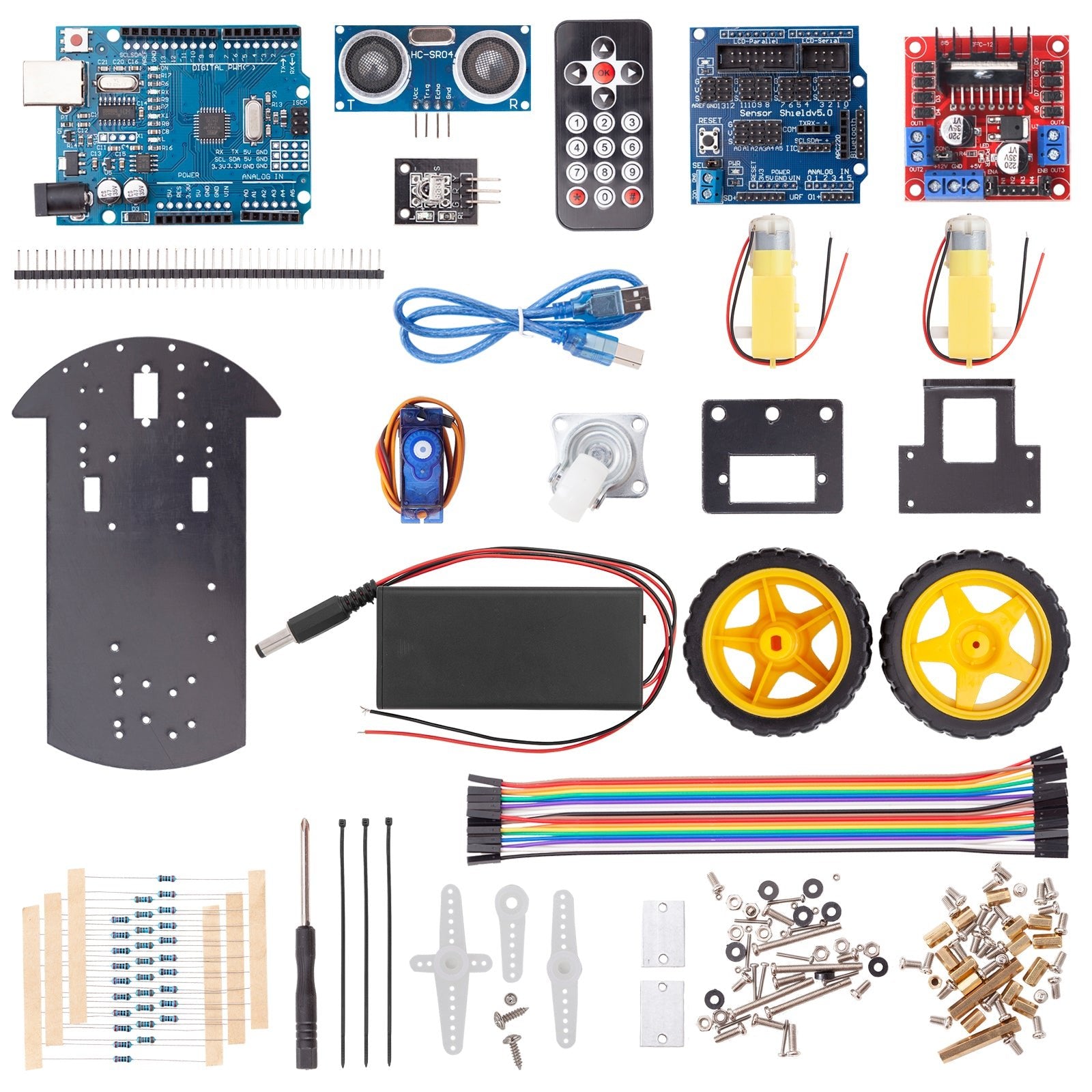
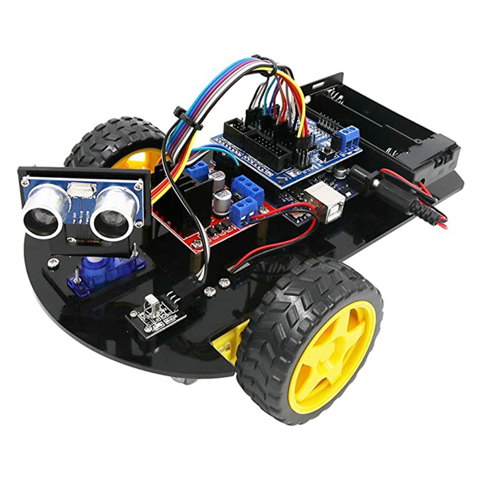
In today's blog post, we want to build a remote-controlled exploration robot from the Acebott Smart Car Kit. The robot is to be controlled using a joystick and show its surroundings on a small display in radar optics.
The ultrasonic sensor, which is already mounted on a servomotor with an acrylic holder, is used to scan the surroundings.
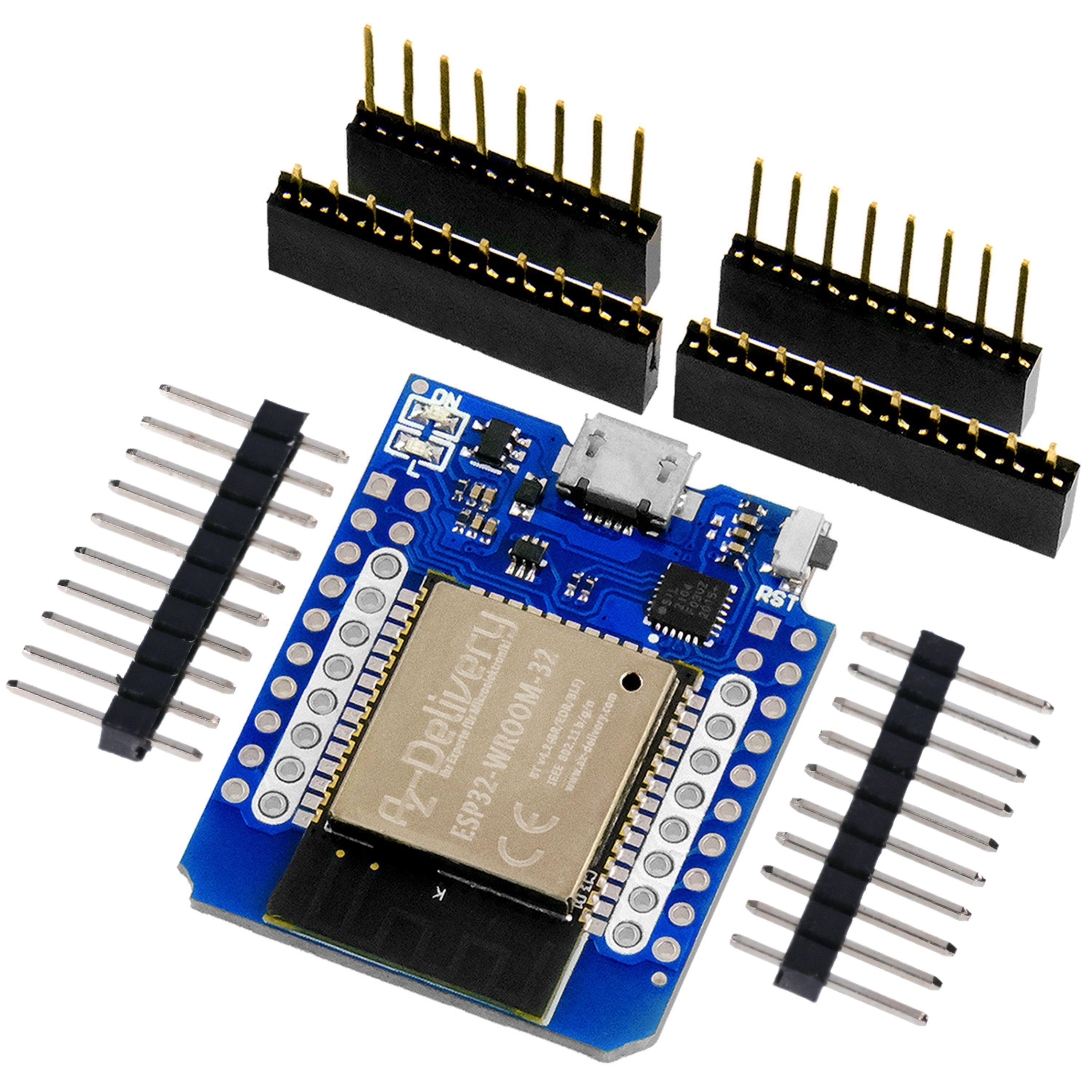
The control system uses the PS2 joystick shield and ESP32 D1 R32 setup that you may already be familiar with from the blog posts on controlling the Bionic Spider robot.
Hardware
If you have already made the modifications to the PS2 Joystick Shield in a previous blog from the Bionic Spider Controller series, you can skip the following paragraph.
For the realization of the project you need:
(optional) 9V block battery + Battery clip
and of course an assembled one Acebott robot car
As the analog inputs of the two joystick axes are connected to GPIO 2 and 4, which are connected to the ADC2, these cannot be used simultaneously with the WLAN module. However, the connections IO 34 and IO35 (ADC1) are located directly next to these, which means that functionality can be easily established via a wire jumper.

Figure 1: Wire bridge between the connections
Connect the connections as shown above.
As the on-board LED is connected to GPIO 2, the pin must be removed here, as the connection would otherwise affect the value of the X-axis voltage.
The same applies to pin D12, as this interferes with the boot process and therefore no boot would be possible with the shield plugged in. The middle button of the joystick is connected to this connection, which means it can no longer be used. If you still want to implement this, it must be reconnected to a free connection.

Figure 2: Shield with modifications
The shield can simply be plugged onto the D1 R32. Make sure that the small switch in the left-hand corner is set to 3v3 otherwise the ESP32 could be damaged by the excessive voltage of 5V.
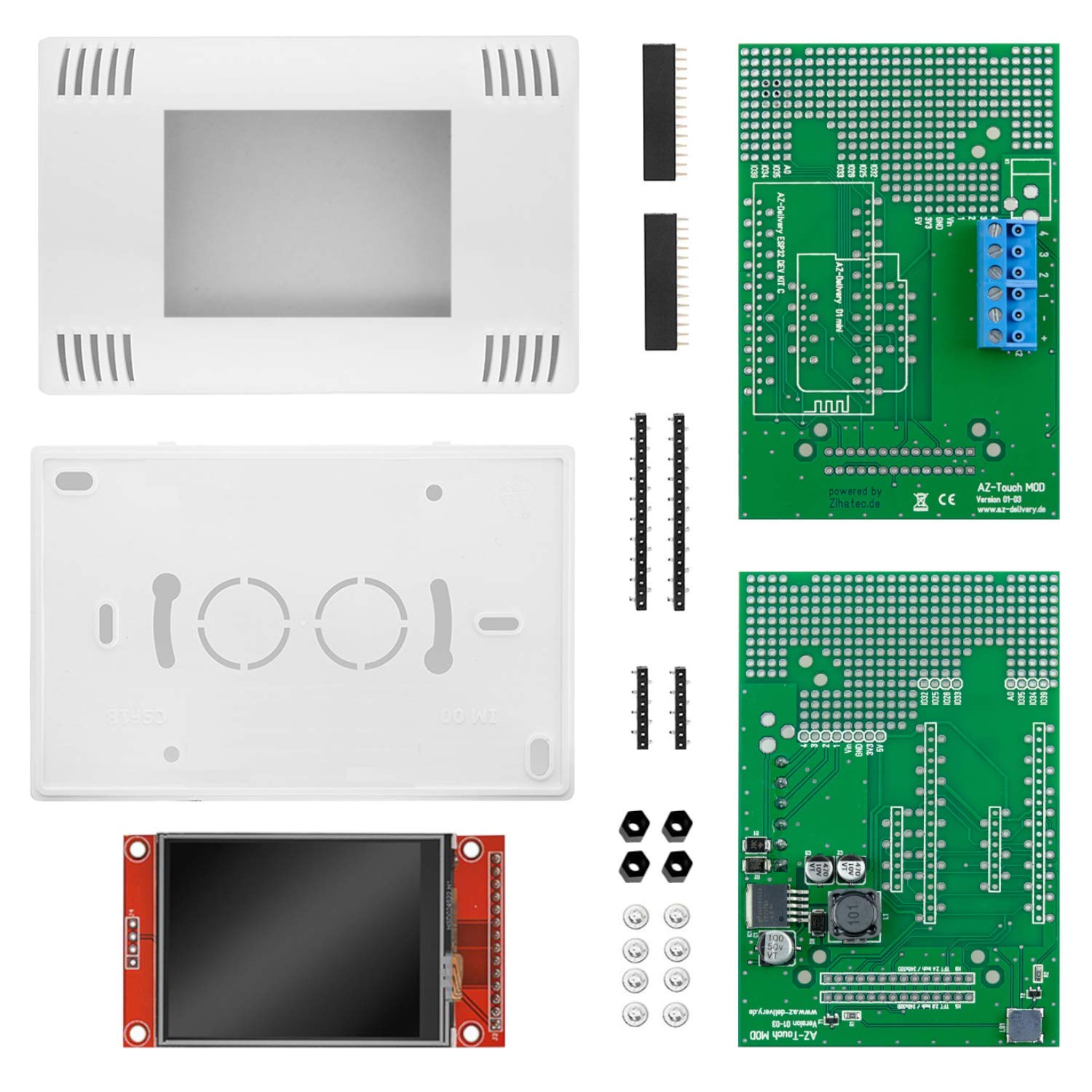
Display extension
As the controller is supposed to display the vehicle's surroundings in the form of a radar screen, as seen in many films, a display is required.
Here we recommend the 1.3" OLED graphic display (SH1106). This is not only a large, easy-to-read graphic display, but also has the right layout for the socket strip of the HC05 module on the shield (top right). This means that the display can be plugged in without any major modifications.
Only the upper SMD resistor next to button A needs to be removed, as this was originally designed to halve the voltage on the RXD pin of the HC05 so that the module is not damaged when operating with the UNO microcontroller.
Image modification
As the microcontroller used (ESP32) has a logic level of 3.3V, communication with the display would no longer work with the halved voltage.
Software
For communication, the data packets are exchanged using UDP. With this communication protocol, the packets are simply sent without checking whether the packet has been received.
Although this makes data exchange very fast, it is also insecure, as it is not possible to determine whether the recipient is actually receiving the data. Communication via a network also enables a greater range compared to ESPnow or Bluetooth, as the network can cover a large area with repeaters and access points.
Basically, the two devices can communicate with each other at any location where you have reception with your smartphone.
The library for UDP communication is already included in the extensive board package for the ESP32.
In addition to the UDP and WiFi library, other external libraries are required, which you still need to install.
These can be downloaded from GitHub as .zip files via the following links and can be used in the Arduino IDE under
Sketch > include Library > Add .zip Library ...
can be selected and installed.
The ESP32Servo, ultrasonic and vehicle Libraries are already included in the .zip file of the instructions. These have also already been installed in the instructions for advanced users.
Code smart car
|
#include <vehicle.h> |
Explanation:
At startup, the ESP32 connects to the WLAN, opens a UDP port and initializes the motors, ultrasonic sensor and servo. In the main loop, it waits for incoming UDP commands and evaluates them as text commands. Depending on the command, the motors are controlled or special functions are executed.
With the BTN_A command, the servo swivels the ultrasonic sensor in steps, measures the distance at each position and saves the angle and distance in a JSON array. Once the scan is complete, the JSON is serialized and sent back to the sender via UDP, after which the servo returns to the middle position.
After each executed action, the ESP32 sends the feedback "RDY" to signal that it is ready for the next command.
You can use the code here download.
Once you have loaded the program onto the microcontroller with the correct WLAN access data, the IP address of the device will be displayed. Make a note of this as it is required by the controller.
Code controller
|
#include <math.h> JsonDocument doc; |
Explanation:
After starting, the ESP32 connects to the WLAN, initializes the OLED display, calibrates the joystick to its middle position and sets the required GPIOs for the buttons. The joystick axes are continuously evaluated in the main loop. If they exceed a threshold value, a direction of travel is determined and sent as a command (e.g. forwards, backwards, left, right), or stop if the joystick is in the center position, via UDP. In addition, special commands can be triggered using the A-F buttons. To avoid multiple transmissions, each command is only sent again after confirmation or a timeout has occurred.
Incoming UDP packets are also evaluated. If the response "RDY" is received, this signals that the receiver is ready for the next command. If the packet contains a JSON object with measurement data instead, this is parsed and displayed as a line display on the OLED. The angle and distance of the measured values represent lines that start from the center of the display. This creates a simple graphical representation of the environment detected by the other ESP32.
The lines are created with the drawLineAngle() function. Here, the end coordinates of the line are calculated using the sine and cosine. You can find a detailed explanation in the blog Retro watch with GC9A01A.
You can use the code here download.
Load the program with the correct access data and IP address of the receiver onto the microcontroller.
Conclusion
If you now press button A on the controller, the display will show you the surroundings in the next 60 cm graphically as a line for each measurement. One pixel corresponds to approximately one centimeter. If you want a wider display radius, you can adjust the controller program accordingly, but you should note the maximum length of 60 pixels.
Of course, this project only lays the foundations for your own extensions and modifications. In addition to scanning the environment, other functions can also be added; the unassigned buttons on the controller shield are available here.
Have fun rebuilding :)