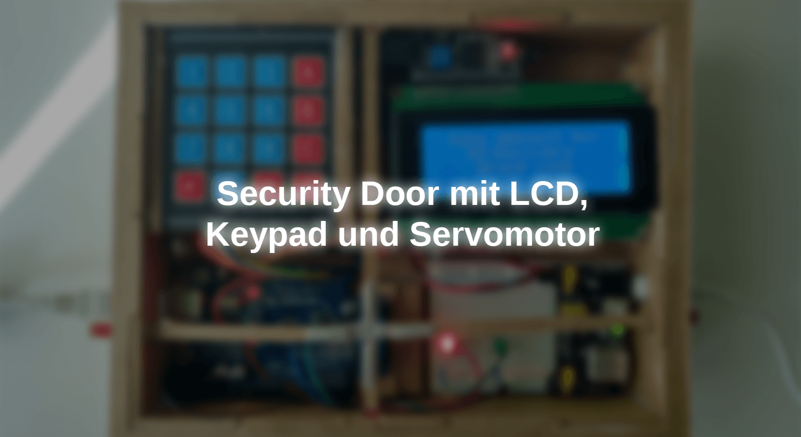
In this project we show a possibility of a circuit for a security door with a few components. This door can be used, for example, in a security box for storing important documents.

Our structure will open the security box by entering an alphanumeric code. This code will be four characters long. We will use an LCD screen to display the numbers as they are pressed on the 4x4 matrix keyboard. We will also display a confirmation, depending on whether the code was entered correctly or incorrectly. We will use a servomotor for the door locking mechanism. We will also install two LEDs. A red LED that shows that the door is closed and locked and another green LED, which indicates that the door is open. We can choose from the keyboard whether the display should remain switched on or off.
As you can see later in the video, we will remove the front of this project to see how the locking system for the door lock moves. This is a simple project with just a few components, but we can do a lot with it. Let's start with the required materials and software.
Required materials:
|
1 |
|
|
1 |
alternative |
|
2 |
|
|
1 |
HD44780 2004 LCD Display Bundle 4x20 characters with I2C interface |
|
1 |
MB 102 Breadboard Kit - 830 Breadboard, power supply adapter 3.3V 5V, 65Stk plug -in bridges |
|
1 |
|
|
1 |
|
|
1 |
Required software
- Arduino IDE
- Liquid Crystal I2C Library (about library administrator)
- Keypad Library (by Chris-A; about library administrator)
- Servo library (integrated)
- Security Door Sketch
Circuit and description of the functionality
As shown in the picture below, the circuit diagram is shown:

As can be seen in the circuit, the servo motor and the LCD display are supplied with separate 5V so that the microcontroller is relieved.
Now we will connect the other components. We start with the 4x4 matrix keyboard, which we connect from PIN D2 to PIN D9 of the microcontroller. We should avoid using the PINS D0 and D1 of the microcontroller. Since we will use the I2C communication with the screen, this bothers the keyboard signals. We use the PINS D10 or D11 for the green and red LED and we connect to PIN D12 of the microcontroller. We use the 330 ohm resistance on the respective anode of the LEDs and the microcontroller.
As already mentioned, we use the I2C bus for communication of the LCD screen, which, as you can read in the documentation of the microcontroller, uses the PINS A4 and A5 to which we use the Pins SDA and SCL of the I2C adapter module of the Connect LCD screen. It is very important to connect the GND pin of the power supply module to the GND of the microcontroller in order to avoid communication errors. Finally, we connect the 5 V-DC power supply.
In the sketch, the code 2255 is preset as the key to opening the safe. This key can be configured so that it contains a code with several numbers. Usually the screen is not illuminated. To activate the lighting, you have to press the # #, the message "Enter The Key" appears and the figures entered appear on the screen. If the four digits result in the right code, this is displayed on the display, the servomotor moves and the green LED lights up to display that the door is open. To close the door, press the *symbol on the keyboard, lock the door pencils and the red LED flashes to indicate that the door is closed. If you make an error when entering the key numbers, you can delete the entered numbers by pressing the * button.
Description of the source code
The first thing that has to be done at the beginning of a sketch is added to the necessary libraries in order to be able to use the components of our projects. In this case, we have to include the library for the LCD screen. In this case we use the LiquidCrystal library with the addition "_i2c". We also bind Keypad.H and Servo.H for communication with the Keypad and the servo.
#include <LiquidCrystal_i2c.H>		          // LCD display library.
#include <Wire.H>                                 // i2c comunications library
#include <Servo.H>			          // servo motor library.
#include <Keypad.H>			          // 4x4 matrix keyboard library.
This is followed by the configuration for the required modules. We start with the instance of an object of our LCD screen. The arguments (parameters) we have to state are: the I2C address of our module, the number of columns of our screen and the number of lines.
LiquidCrystal_i2c LCD(0x27,20,4);
We then start with the declaration of the necessary variables of our project, these are: the drawing position variable for comparing our configured button with the button entered via the keyboard, the position of the first character of the button to be typed on the LCD screen, the status variable (not Correct = 0 and correct = 1) of our button and the variable for the status of the backlighting of our LCD screen.
LiquidCrystal_i2c LCD(0x27,20,4);	          // LCD display object implementation.
intimately Key_Position_numbers = 0;                     // Variable for position of the Opening Code Numbers.
intimately cursor_position = 8;                          // variable for initial position of the first number of the opening code on lcd.
intimately status_key_number = 0;                        // Variable for Opening Code Numbers Correct (1), Wrong (0).
intimately lcd_light = 0;                                // variable for lcd backlight on (1), off (0)
In order to use the servomotor, we instance an object of this servomotor and define a variable to save the axle positions. The type of variable is an integer because we will use full number of degrees.
Servo servo_lock;			          // servo motor object implementation
intimately servo_position = 0;			          // variable servo engine position definition
The module that still has to be configured is the 4x4 film keyboard. This is a little more complex. For the number of lines and columns, we define two constants, which we assign 4 lines and 4 columns.
const byte rows = 4;     		          // Number of keyboard rows
const byte columns = 4;    		          // Number of keyboard columns
Then we have to create two arrays to define the microcontroller pins with which the lines and columns of the keyboard are connected. Once again, the note that the pins D0 and D1 are blocked by using the i2C interface.
byte rows_pins[] = {9,8,7,6};   	          // Microcontroller Pins Connecting the keyboard rows.
byte columns_pins[] = {5,4,3,2};   	          // Microcontroller Pins Connecting the Keyboard Columns.
Next we configured a matrix (multi -dimensional array) with the number of lines and columns. The array reflects the keyboard layout. If you select a line and column number and cross it, you get a button. Remember that the coordinates in programming start at 0 (zero). So if we select line 2 and column 1, we receive the 8 button.
char keys [rows] [columns] = {		         // Matrix with the positions of the keys on the keyboard.
    {'1','2','3','A'},
    {'4','5','6','B'},
    {'7','8','9','C'},
    {'*','0','#','D'}
};
With all previously configured parameters, we can now implement an object for our keyboard. We call the object mykeyboard. As an arguments, the matrix with the layout of the keys, the variables of the microcontroller pins, to which the lines and columns are connected, and the variables with the number of lines and columns that our keyboard has.
Keypad mykeyboard = Keypad(make -up(keys), rows_pins, columns_pins, rows, columns);
To define the safe's opening code, we configure an array with the length of the desired characters, this number is between angular brackets, in our case it has a length of 4 characters. Within the array we write the desired characters between simple quotes and separated by commas, in this project the code 2255.
char Opening_code[4] = {'2','2','5','5'};
The last configuration that still has to be determined are the pins D10 and D11 of the microcontroller to which we will connect the green or red LED.
intimately green_led = 10;
intimately red_led = 11;
After we have configured the components and modules of our circuit, we have to program the initialization or the initial state when we connect the voltage or reset the microcontroller. This happens in the set up()-Method of sketch. We start with the initialization of our LCD screen and without lighting in the initial configuration.
LCD.init();
LCD.Nobacklight();
The LEDs follow after initialization of the screen. In the first two lines we configure these pins as an output. The next two lines are the initial state of the LEDs, since the door is closed and locked, we configure the output of the red LED pin to high levels so that the LED lights up. The PIN of the green LED is configured with low level and thus off.
pin mode(green_led,OUTPUT);		    // Configuration of the Microcontroller Pin to the Green Led Pin as Output.
pin mode(red_led, OUTPUT);		    // Configuration of the microcontroller pin to the red led pin as output.
digital(red_led,HIGH);  		    // initial status of red led on.
digital(green_led, Low);  		    // Initial status of green led off.
Now we have to initialize the servo engine in the starting position. To do this, we will first inform the microcontroller the PIN to which we connect the signal to the servomotor, it is PIN D12. We also have to send the value to the degree of position in which it should be in place if the microcontroller is initialized. In this case, that's 90 degrees. This value depends on the position in which we install the servo engine in the door.
servo_lock.Attach(12);
servo_lock.write(90);
The following lines of the code are the messages that will appear on the screen. As already mentioned, the programming coordinates begin at 0 and not at 1, so that the first line indicates that the cursor is placed in the first line and the first column of the screen. In the next line we indicate the message that is to be displayed. The other lines are similar, only that in the fourth line we are the cursor in the position cursor_position put. However, nothing more is displayed, as this line serves to show the entered characters.
LCD.setcursor(0,0); 			          // cursor position at the 0 position of the first Row of the lcd display.
LCD.print("Safe Deposit Box");	          // Text to be displayed in the first Row.
LCD.setcursor(0,1);			          // cursor position at the 0 position of the second row of the lcd display.
LCD.print("AZ-Delivery");	          // Text to be displayed in the Second Row.
LCD.setcursor(0,2);   			          // cursor position at position 0 of the third row of the lcd.
LCD.print("Enter code to Open"); 	          // Text to be displayed in the Third Row.
LCD.setcursor(cursor_position,3); 	          // cursor position at position 8 of the forth row of the lcd.
The next method we have to program is Loop (). The block that runs constantly. If we look at this method we can see that there are 4 conditions. One is executed when the *button is pressed (delete characters), an activates the servo motor for locking and two other conditions are executed when the #button is pressed (backlighting of the display). Let us explain the Loop () lines.
The first and very important line is the declaration of a "Sign" variable to save the value of the pressed button.
char keystroke = mykeyboard.getkey();
The first condition is carried out if the previously declared variable is not empty. If this variable contains any data, the following condition checks whether the pressed buttons are not the character extinguishing button or the button for activating the backlight and whether the correct opening code is not complete. Then the pressed sign is written on the screen and the cursor is placed to the next position.
    char keystroke = mykeyboard.getkey();
    IF (keystroke != 0) {
	IF (keystroke != '#' && keystroke != '*' && status_key_number == 0) {
    	    LCD.print(keystroke);
    	    cursor_position++;
If the comparison shows that four characters have been entered and correspond to the stored code, the following condition is carried out. This sets the position of the cursor in the first position of the third line of the screen and the message "valid code" is issued. Then the position becomes cursor_position used and set in the fourth line. The variable status_key_number Is a 1 train. This means that the code entered is correct. The condition of the LEDs is changed, the green LED lights up. Then a loop runs so that the servo engine moves from the 90-degree position into the 180-degree position in a slow movement and unlocks the door pencils.
IF (Key_Position_numbers == 4) {
      LCD.setcursor (0,2);
      LCD.print ("Valid code");
      LCD.setcursor(cursor_position,3);
      status_key_number = 1;
      digital(red_led,Low);
      digital(green_led, HIGH);

      for (servo_position = 90; servo_position <= 180; servo_position += 1) {
            servo_lock.write(servo_position);
            delay(15);
      }
}
If the comparison results in a failure and the cursor position for the character input is more than four positions, the position in cursor_position changed. First of all, the Cursor position variable is assigned the value 8, the following variable Key_Position_numbers is the position of the comparison mark of our button and is set to 0 to "reset" it. Next we have to clean up the characters. To do this, we place the cursor on the LCD screen at the position of the value of the variables cursor_position, which we previously assigned 8 in the fourth line, write four spaces and place the cursor back in the previous position (cursor_position). This deletes the line.
IF (cursor_position > 11) {
   cursor_position = 8;
   Key_Position_numbers = 0;
   LCD.setcursor(cursor_position,3);
   LCD.print("    ");
   LCD.setcursor(cursor_position,3);
The next condition checks the condition of the variables of our button, which we assigned the value 0 at the beginning of the sketch. In line 3 of our LCDS, the message "False Code" shows for 4 seconds, then the message "Enter Code to Open" again. Then the cursor in line 4 is at the position cursor_position positioned. In this case again 8.
IF (status_key_number == 0) {
      LCD.setcursor (0,2);
      LCD.print ("Wrong code");
      delay(4000);
      LCD.setcursor (0,2);
      LCD.print ("Enter code to Open");
      LCD.setcursor(cursor_position,3);
}
Now we will program the backlight of the LCD screen, for which we will also use conditions. We have declared a variable (lcd_light) for the condition of the backlight of the screen. If this 0 is, the screen is switched off and if it is 1, it is illuminated. In the first condition of the LCD backlight, when we press the #key and the variable has the value 0, the screen is illuminated. We set the variable to 1 to keep the screen on. Then we delete the content of the press variable by giving it the value 0 so that too key is changed without pressing. In this way, the microcontroller will then wait for pressing a button.
IF (keystroke == '#' && lcd_light==0) {
      LCD.backlight();
      lcd_light=1;
      keystroke =0;
}
If, on the other hand, when pressing the # key the variable lcd_light has the value 1, this means that the screen is illuminated. Then the following condition is carried out, which switches off the backlight of the screen and the value 0 in the variable lcd_light Saves.
IF (keystroke == '#' && lcd_light==1) {
        LCD.Nobacklight();
        lcd_light=0;
}
All that remains is the functionality of the *button, with which we can lock the door and delete the numbers of the opening key. In the IF statement, the number of characters entered is first deleted. The cursor position is set back to 8. The condition of the opening variable is set as not correct. On the LCD screen we position the cursor in the third line, so that the text that prompted to enter the opening code is displayed. Then we position the cursor at the point where the code was entered and delete all the characters. Finally we let the red LED light up and the servo moves to lock the door pencils if it was not closed beforehand. I briefly explain why we programmed the loop within a condition. As you can see in the condition, the positions of the servomotor 180 and 90 stand as loop parameters.
If we did not insert the condition, the servo engine, even if it is in the position of 90 degrees, would move to 180 degrees and then to 90 degrees. We have programmed that the loop is carried out when the servomotor is in a position of more than 99 degrees, i.e. when the door is open while the loop is executed. If the door is already closed and locked, the servo position is 90 degrees. Then only the characters on the display are deleted.
IF (keystroke == '*') {
      Key_Position_numbers = 0;
      cursor_position = 8;
      status_key_number = 0;
      Key_Position_numbers = 0;
      LCD.setcursor(0,2);
      LCD.print("Enter code to Open");

      LCD.setcursor(cursor_position,3);
      LCD.print("    ");
      LCD.setcursor(cursor_position,3);

      digital(red_led,HIGH);
      digital(green_led, Low);

      IF (servo_position >= 99) {
            for (servo_position = 180; servo_position >= 90; servo_position -= 1) {
                  servo_lock.write(servo_position);
                  delay(15);
            }
      }
}
Complete source code as download
I hope that you like this project, you enjoy it and find it useful.


4 comments
Andreas Wolter
@Jana Reichert: da hier die setup() und loop() nicht erkannt werden, scheint grundlegend etwas nicht zu stimmen. Es scheint, als hätten Sie die Arduino IDE aus dem MS Store installiert (das interpretiere ich aus dem Ordnerpfad der Fehlermeldung). Das könnte eine Fehlerquelle sein. Ich empfehle die Installation von der Webseite: https://www.arduino.cc/en/software und dann auch vorzugsweise erst einmal die Legacy 1.8.x
Ich kenne Ihre Installation nicht. Aber es sieht für mich so aus, dass man da zuerst ansetzen sollte.
Grüße,
Andreas Wolter
AZ-Delivery Blog
Jana Reichert
Hello, when I try to use the scetch I get this error message, can someone tell me how I can fix it?
Arduino: 1.8.19 (Windows Store 1.8.57.0) (Windows 10), Board: “Arduino Uno”
C:\Users\Lenovo\AppData\Local\Temp\ccfR8uDf.ltrans0.ltrans.o: In function `main’:
C:\Program Files\WindowsApps\ArduinoLLC.ArduinoIDE_1.8.57.0_x86__mdqgnx93n4wtt\hardware\arduino\avr\cores\arduino/main.cpp:43: undefined reference to `setup’
C:\Program Files\WindowsApps\ArduinoLLC.ArduinoIDE_1.8.57.0_x86__mdqgnx93n4wtt\hardware\arduino\avr\cores\arduino/main.cpp:46: undefined reference to `loop’
collect2.exe: error: ld returned 1 exit status
Mehrere Bibliotheken wurden für “Servo.h” gefunden
Benutzt: C:\Users\Lenovo\Documents\Arduino\libraries\Servo Nicht benutzt: C:\Program Files\WindowsApps\ArduinoLLC.ArduinoIDE_1.8.57.0_x86__mdqgnx93n4wtt\libraries\Servoexit status 1
Fehler beim Kompilieren für das Board Arduino Uno.
Andreas Wolter
@Eugene Allard:
I think that the library Keypad.h has not been installed. Only with it can the object Keypad myKeyboard be instantiated. There, the function makeKeymap(keys) is called when it is created.
Best regards,
Andreas Wolter
AZ-Delivery Blog
Eugene Allard
Hallo als ik de schets wil gebruiken krijg ik deze fout melding kunt u mij vertellen hoe ik dit op kan lossen.
Niet gebruikt: C:\Users\Zwart\Documenten\Arduino\libraries\Arduino-LiquidCrystal-I2C-library-master
exit status 1
‘makeKeymap’ was not declared in this scope