The building instructions and further information can be found in the Free e-book.
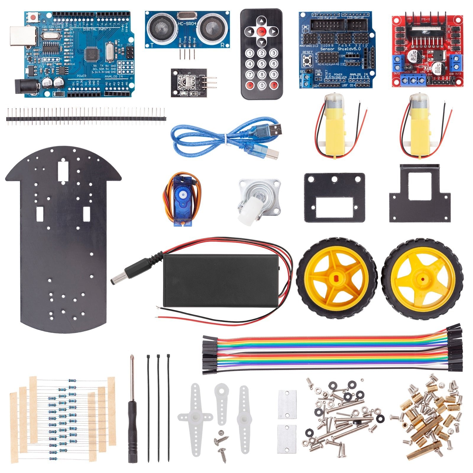
Remember the blog series on the subject of Robot Car or Smart Car? In the spring of 2021 we highlighted this topic from various sides and also showed various control options. Everything that was missing at the time was the right hardware in the range. Now comes a Robot Car Kit, that leaves nothing to be desired. Everything there to implement a remote-controlled smart car.


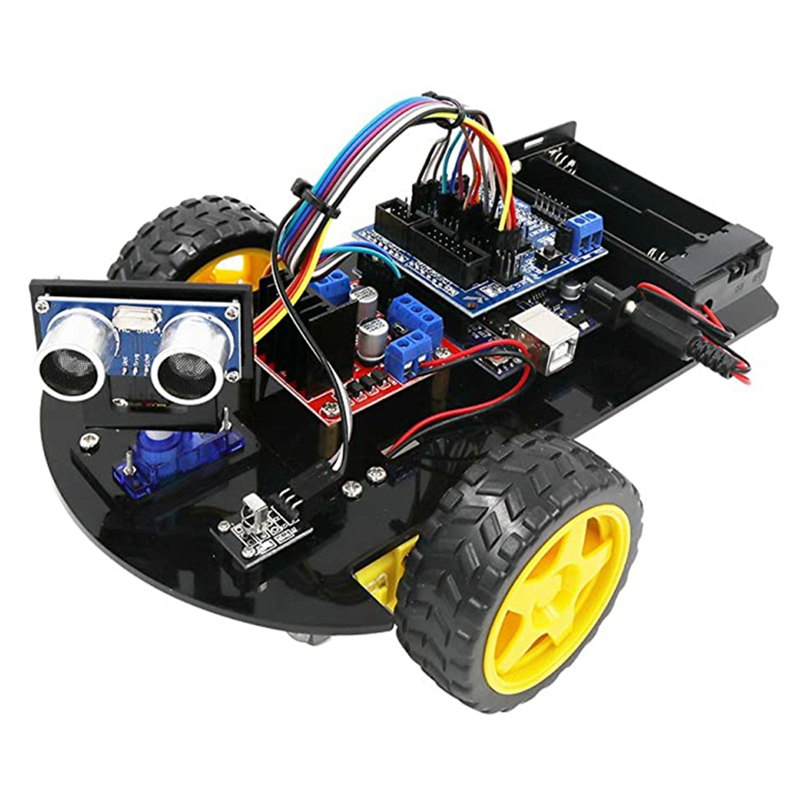
In the following, I would like to present the less-known components: the Motor Controller Board with L298N, the Sensor Shield V5, and a simple remote control with IR remote control. What inspires me most inspires the rectangular recess in the chassis for the installation of a small servo on which the distance sensor HC-SR04 is screwed. This would have to be possible to let the smart car react even better to obstacles and thus get a little closer to autonomous driving. I had never seen this anywhere and I have no solution for the best possible use of this now-swiveling sensor.
Motor Controller Board
The Motor Controller Board with the IC L298n had already had Jörn Weise in his blog post about the H-bridge presented. You can see from the large heat sink that this building block can also provide significantly larger DC engines than the widespread small yellow engines can supply them with excitement. As a reminder: No microcontroller delivers so much electricity to the GPIOs that the engines can turn. Only the control signals come from here. The motor controller has three tasks: firstly, provide enough electrical energy (voltage and current!) To enable the polarity to change the change for the direction of direction (H-bridge) and thirdly to control the speed (speed of the engine). The signals for the polarity and speed come from the microcontroller.

The blue screw connections (Terminal Blocks) are the connections to the "outside world". On the left and right two connections for the two engines. If the direction of rotation of the engines is not right in the end, you have two options: either overflow or change the follow-up assignment in the sketch. The three-way block serves the external power supply: On the far left, the plus pole of the battery/battery is connected, in the middle of the minus pole (always connected to GND on the microcontroller), and on the right there is a 5V output to optionally supply the microcontroller. If the external voltage is smaller or 12 volts, the jumper remains above the terminal block, above 12 volts it is removed.
The pins at the bottom right of the picture are the six connections to the microcontroller (three per motor). From left to right: Ena - In1 - In2 - In3 - In4- Enb.
In the delivery state, jumpers are located on the two enable pins Ena and Enb. We remove this so that we can feed the respective PWM signals here. In1 up to in4 can be connected to normal GPIO outputs, and ENA and ENB go to PWM-capable pins (these are those with the Tilde ~).
In the example sketch (see below), the engine connections are defined as follows:
// motor pins
int ena = 6;
int in1 = 9;
int in2 = 8;
int Enb = 5;
int in3 = 7;
int in4 = 10;
As I said, if the side or direction of rotation does not fit, you can change the occupancy here or reopen the connections at the Terminal Block.
Sensor Shield V5.0
As usual, the Arduino Sensor Shield V5.0 is plugged into the microcontroller with ATMEGA328 and offers different connection options, including multiple assignments of the pins.

In the middle, there are all digital and analog inputs and outputs. The nice thing is that in addition to every PIN, the connections for ground and the supply tension are also available so that you finally have enough options here.
On the right in the picture are the COM connections, also for Bluetooth. The connections for the power supply are also nice here, but the signal lines on D1 and D0, i.e. TX and RX, go. This means avoiding the serial monitor in operation and separating these connections when uploading the sketch. I personally prefer software series of any other pins.
At the bottom right is an Ultra Sonic interface that uses the analog inputs A0 and A1. You can do it, because these are also digital inputs or outputs, you just have to know if you want to use the analog inputs.


Optional structure with display
The connections for the SD card interface were the most exciting (because new to me) LCD12864. An SD card reader makes absolute sense for a shielded sensor if you want to record and save measurement data. With the example sketch datalogger, I only had to
Const int chipselect = 4; change in Const int chipselect = 10;
I was surprised at how quickly and easily it was.

In the LCD12864 I chose the serial connection (in the picture at the top right) and the explanations of the eBooks followed. Unlike the displays LCD1602 and 2004, which have predefined areas for signs, this is a graphic display with a resolution of 128x64 = 8192 pixels. This requires another program library, which is often used for TFT displays and is therefore known for TFT. As so often, there are sample programs for this library. In the eBook, the example sketch graphic test has been shortened to the essentials.
After including with
#include
the two slashes are removed in the following line and pins 4, 3, 2 are used instead of the usual spi pins.
U8g2_st7920_128x64_f_sw_spi U8G2 (U8G2_R0, 4, 3, 2); // instead of 13, 11, 10
We connect SCL = 4 to LCD-PIN E, MOSI = 3 to LCD-R/W and CE = 2 to LCD-RS.


Conclusion Sensor Shield: Very functional add-on, which is absolutely useful for connecting several sensors, an SD card reader, and the LCD12864, for the spartan execution of a robot car with six GPIOs for the engines and a GPIO for the IR sensor and with others Projects better used.
IR remote control
After these experiments, I tried the IR remote control. I discovered a very good program library. I have her with mine Robot Car Sketch with the self-made remote control with LCD-Kypad and combined the 433 MHz transceiver.
I developed code that is converted into driving stages. Due to the use of a joystick in other variants, the driving level stands at Code 505. The hundred-point increases the speed when driving forward from 6 to 10, and when reversing from 4 to 0. Cornering is initiated by increasing or reducing a job.
These changes can be implemented wonderfully with the cursor buttons of an IR remote control. The program queries which button was pressed and adjusts the code accordingly. If the maximum or minimum has already been reached, nothing will be changed. The red OK button in the middle leads to a quick stop with code 505, all other signals are ignored.
In order to obtain many options for the use of Armin Joachimsmeyer's IR library, I have largely incorporated them into my sketch. That means that his help files Pinding definition sandmore.h must be present in the same sketch directory. If you want to optimize space, you can certainly define the IR-PIN = 2 in the main program.
The distance sensor HC-SR04 is connected to pins 3 and 4, the servo of pin 12.
Source code
In the Setup () function, the servo is with myservo.attach (12); Initialized, tested, and aligned in the middle. In order not to disturb the IR sensor, the servo will then be back with you myservo.detach (); Deactivated.
To prevent collisions, in everyone Loop () The self-defined function of distance cemetasuring () called. At distances below 10 cm, the engines are automatically stopped and the code is set to 505 (standstill). At this point, the code can be expanded to achieve a certain autonomy when driving, e.g. swiveling the servo 45 ° and 90 ° to the left and right, finding a better way out, reversing a few cm, and curving. I first left it at the quick stop.
Here the sketch (Download)
/* Demo Program for Robot Car With Ir Remote Controller * Based on simplereceiver.cpp, which is part of arduino-iremote library * https://github.com/Arduino-IRremote/Arduino-IRremote. * With License Copyright (C) 2020-2022 Armin Joachimsmeyer * * Permission is HEREBY Granted, Free Of Charge, To Any Person Ocise A Copy * of this software and associated documentation files (the "software"), to deal * In the software with restriction, including with word limitation the rights * to use, copy, modify, merge, publish, distribute, sublicense, and/or sell * Copies of the Software, and to Permit Personal to Whom the Software is Furnished * to do so, subject to the following conditions: * * The above copyright notice and this permission notice shall be included in all * Copies or substantial portions of the software. * * The Software is Provided "As is", Without Warranty of Any Kind, Express Or Implied, * Including but not limited to the Warranties of Merchahantibitability, Fitness for A * Particular Purpose and Noninfringement. In No Event Shall the Authors or Copyright * Holders Be Lible for Any Claim, Damages or Other Liability, Whether in an Action of * Contract, Tort or OtherWise, Arising from, out of or in Connection with the software * Or the use or other dealings in the software. * ************************************************************************************ */ /* * Specify which protocol (s) should be used for decoding. * If no protocol is defined, all protocols are active. * For first use uncomment line //#define info */ //#define decode_denon // including Sharp //#define decode_jvc //#define decode_kaseikyo //#define decode_panasonic // The same as decode_kaseikyo //#define decode_lg #define Decode_nec // included Apple and Onkyo - small remote control //#define decode_samsung //#define decode_sony //#define decode_rc5 //#define decode_rc6 // Works fine with my philips dvd remote controller //#define decode_bosewave //#define decode_lego_pf //#define decode_magiquest //#define decode_whynter //#define decode_distance // Universal decoder for pulse width or pulse distance protocols //#define decode_hash // Special decoder for all protocols //#define debug // Activate this for lots of lovely debug output from the decoders. //#define info // to see value information from universal decoder for pulse width or pulse distance protocols #include <Arduino.H> /* * Define macros for input and output pin etc. */ #include "Pindefin Finitionsandmore.H" #include <Crazy.Hpp> #include <Servo.H> Servo myservo; // Create servo object to control a servo intimately POS = 90; // variable to store the servo position // motor pins intimately ENA = 6; intimately In1 = 9; intimately IN 2 = 8; intimately ENB = 5; intimately In3 = 7; intimately In4 = 10; intimately X = 0; intimately y = 0; intimately leaf = 0; intimately right = 0; intimately code = 505; // int coeread = 505; intimately speed = 0; float factor = 0.65; // correction for driving levels // distance sensor HC-SR04, trigger at pin 4, echo at pin 3 intimately trigger=4; // Trigger-Pin intimately echo=3; // echo-pin long travel=0; // Variable Traveltime, Initally 0 long distance=0; // Variable distance, initially 0 void setup() { myservo.attach(12); // attaches the servo on pin 12 to the servo object myservo.write(0); // tell servo to go to position in variable 'pos' delay(500); myservo.write(180); // tell servo to go to position in variable 'pos' delay(500); myservo.write(90); // tell servo to go to position in variable 'pos' delay(500); myservo.detach(); // absolutely necessary, because servo disturbs IR receiver ! // initialize digital pins as an output. pinMode(IN1, OUTPUT); pinMode(IN2, OUTPUT); //Motor 1 pinMode(IN3, OUTPUT); pinMode(IN4, OUTPUT); //Motor 2 // Distance Sensor pinMode(trigger, OUTPUT); // Trigger-Pin is output pinMode(echo, INPUT); // Echo-Pin is input Serial.begin(115200); // Just to know which program is running on my Arduino Serial.println(F("START " __FILE__ " from " __DATE__ "\r\nUsing library version " VERSION_IRREMOTE)); // Start the receiver and if not 3. parameter specified, take LED_BUILTIN pin from the internal boards definition as default feedback LED IrReceiver.begin(IR_RECEIVE_PIN, ENABLE_LED_FEEDBACK); Serial.print(F("Ready to receive IR signals of protocols: ")); printActiveIRProtocols(&Serial); Serial.print(F("at pin ")); Serial.println(IR_RECEIVE_PIN); Serial.println("Motor test!"); Serial.println(" "); } // end setup void loop() { distancemeasuring(); if (IrReceiver.decode()) { // Print a short summary of received data IrReceiver.printIRResultShort(&Serial); if (IrReceiver.decodedIRData.protocol == UNKNOWN) { // We have an unknown protocol here, print more info IrReceiver.printIRResultRawFormatted(&Serial, true); } Serial.println(); delay(100); // Entprellen, keine schnelle Wiederholung /* * !!!Important!!! Enable receiving of the next value, * since receiving has stopped after the end of the current received data packet. */ IrReceiver.resume(); // Enable receiving of the next value /* * Finally, check the received data and perform actions according to the received command */ int IR_Signal = IrReceiver.decodedIRData.command; Serial.print("IR_Signal = "); Serial.println(IR_Signal,HEX); if (IR_Signal == 0x46) { if (code<911) code = code + 100; Serial.print("Code = "); Serial.println(code); } else if (IR_Signal == 0x15) { if (code>99) code = code - 100; Serial.print("Code = "); Serial.println(code); } else if (IR_Signal == 0x43) { if ((code-100*int(code/100))<10) code = code + 1; Serial.print("Code = "); Serial.println(code); } else if (IR_Signal == 0x44) { if (code-100*int(code/100) > 0) code = code - 1; Serial.print("Code = "); Serial.println(code); } else if (IR_Signal == 0x40) { code = 505; Serial.print("Code = "); Serial.println(code); } else { Serial.print("invalid Code"); } motor(); } } // end loop void distancemeasuring() { digitalWrite(trigger, LOW); //Hier nimmt man die Spannung für kurze Zeit vom Trigger-Pin, damit man später beim senden des Trigger-Signals ein rauschfreies Signal hat. delay(5); //travelTime: 5 Millisekunden digitalWrite(trigger, HIGH); //Jetzt sendet man eine Ultraschallwelle los. delay(10); //Dieser „Ton“ erklingt für 10 Millisekunden. digitalWrite(trigger, LOW);//Dann wird der „Ton“ abgeschaltet. travelTime = pulseIn(echo, HIGH); //Mit dem Befehl „pulseIn“ zählt der Mikrokontroller die Zeit in Mikrosekunden, bis der Schall zum Ultraschallsensor zurückkehrt. distance = (travelTime/2) * 0.03432; // Now you calculate the distance in centimeters. First you share the time through two (because you only want to calculate one route and not the route back and forth). The value is multiplied by the sound speed in the unit centimeter/microsecond and then gets the value in centimeters. IF (spacer >= 500 || spacer <= 0) { Serial.print("No measured value"); // Then the serial monitor should issue "no measured value" because measured values in these areas are wrong or imprecise. return; } Else IF (spacer <10) { code = 505; Analogwrite(ENA,0); Analogwrite(ENB,0); Serial.print(); Serial.print("Distance below 10 cm"); Serial.print(); return; } Else { return; } } void engine() { intimately Speed level[11]={-255,-210,-165,-130,-100,0,100,130,165,210,255}; y = intimately(code /100); X = code - 100*y; speed = Speed level[y]; Serial.print("Code ="); Serial.print(code); Serial.print("Y ="); Serial.print(y); Serial.print("X ="); Serial.print(X); Serial.print("Speedl ="); Serial.print(speed); // correction of the driving levels for cornering IF (X==0){ right = speed+160; leaf = speed-160; } Else IF (X==1){ right = speed+120; leaf = speed-120; } Else IF (X==2){ right = speed+90; leaf = speed-90; } Else IF (X==3) { right = speed+60; leaf = speed-60; } Else IF (X==4) { right = speed+30; leaf = speed-30; } Else IF (X==6) { right = speed -30; leaf = speed+30; } Else IF (X==7) { right = speed-60; leaf = speed+60; } Else IF (X==8) { right = speed-90; leaf = speed+90; } Else IF (X==9) { right = speed-120; leaf = speed+120; } Else IF (X==10) { right = speed-150; leaf = speed+150; } Else { right = speed; leaf = speed; } // Entering the driving levels for "Left" and "Right" Serial.print("Left ="); Serial.print(leaf); Serial.print("Right ="); Serial.print(right); IF (leaf < 80 && leaf > -80) { Analogwrite(ENA,0); } IF (right < 80 && right > -80) { Analogwrite(ENB,0); } IF (leaf>=80) { IF (leaf>255) leaf=255; digital(In1,1); digital(IN 2,0); leaf = factor*leaf; Analogwrite(ENA,leaf); Serial.print("Left*factor ="); Serial.print(leaf); } IF (right>=80) { IF (right>255) right=255; digital(In3,1); digital(In4,0); right = factor*right; Analogwrite(ENB,right); Serial.print("Right*factor ="); Serial.print(right); } IF (leaf<= -80) { IF (leaf<-255) leaf=-255; digital(In1,0); digital(IN 2,1); leaf = -factor*leaf; Analogwrite(ENA,leaf); Serial.print("Left*factor ="); Serial.print(leaf); } IF (right<= -80) { IF (right<-255) right=-255; digital(In3,0); digital(In4,1); right = -factor*right; Analogwrite(ENB,right); Serial.print("Right*factor ="); Serial.print(right); } }
Conclusion
Robot Car Kit, which is worth the price and well equipped, with the servo for the distance sensor a big step towards autonomous driving. However, there are disorders of the IR receiver when operating the servo. However, this is easy to avoid by measuring either the distances at a standstill, or using Bluetooth, 433MHz, or 2.4 GHz transceiver instead of the IR remote control.


24 comments
Mel
Das ist kein Modell für Anfänger.
Die Komponenten im Einzelnen funktionieren gut.
Das Zusammenspiel im Arduino Uno ist eine Herausforderung, die Durchhaltevermögen und Vorwissen erfordert.
Meine Lösung eines ‘autonom’ fahrenden Roboters ist: https://gitlab.com/in_c/robovit
Bedient Euch!
Karel Svetek
I completely agree that this set is intended for learning and getting to know electronics and programming. If you just want a toy, there are enough simple toys on the market. My experience shows that children love challenges and are very skilled at assembling, often more than older ones. Such a set is definitely a good start.
Andreas Wolter
@Wolfgang Gerber: mit diesem Sketch sollte das Robot Car per IR Fernbedienung bedient werden können. Der Sensor dient der Notabschaltung.
Die Beiträge dienen der Inspiration zum Selberbasteln. Es sind keine fertigen Spielzeuge, sondern man muss sich damit auseinandersetzen. Damit man trotzdem einen zügigen Einstieg und erste Erfolgserlebnisse hat, bieten wir die Blogbeiträge an. In diesem Beitrag finden Sie Links zu anderen Beiträgen, die sich ebenfalls mit dem Robot Car beschäftigen. Sie finden in der Suche auch noch andere, die hier nicht verlinkt sind.
Grüße,
Andreas Wolter
AZ-Delivery Blog
Wolfgang Gerber
Hallo, der Zusammenbau hat so weit geklappt. Das Sensorshield ist allerdings absolut überflüssig. Wozu soll das gut sein? Nur um die 3 Plus- und Minusleitungen leichter anschließen zu können? Es wird zwar in der Anleitung und auf dem Titelbild gezeigt. Beim Zusammenbau und Schaltplan taucht es aber nicht mehr auf. Der Arduino hat im Gegensatz zum Original freie +/- Anschlüsse. Da habe ich einfach passende Pins eingelötet und damit auf das Shield verzichten können. Nun ist alles fertig. Der Selbstfahrsketch ist drauf. Das Einzige, was hier passiert ist, dass sich der Ultraschallsensor hin- und herbewegt. Messwerte der US-Sensoren kommen im SerialMonitor. Fahren will das Ding aber nicht. Zur Inbetriebnahme fehlen leider alle nötigen Tipps. Die Anleitung fängt zwar gut an. Aber ab der Fertigstellung der Montage ist einfach Schluss. So habe ich mir das nicht vorgestellt. Ich bin nicht nur enttäuscht, sondern richtig verärgert. Der Enkel hat jetzt seinen Robocar und kann nichts damit anfangen. Ich habe schon stundenlang im Netz gesucht, aber keine brauchbaren Infos gefunden. Kennt da jemand noch ein paar Links zu weiterführenden Tipps? Nicht zur Arduinoprogrammierung. Das geht. Wir suchen brauchbare spezielle Scripte, die das Ding zu irgendwelchen “Aktionen” bewegt, ausser den US-Sensor hin- und herzubewegen. Für eine komplette Eigenentwicklung fehlt mir leider die Zeit und der Enkel ist noch nicht so weit. Ich hatte erwartet, dass AZ da was Brauchbares an Basis mitliefert.
Andreas Wolter
@Bigi: Vous devez assembler la Robot Car, installer l’IDE Arduino, télécharger le sketch et l’ouvrir dans l’IDE Arduino. Ensuite, vous devez encore installer quelques bibliothèques dans l’IDE Arduino. Enfin, il faut compiler le code et le charger sur le microcontrôleur.
Meilleures salutations,
Andreas Wolter
AZ-Delivery Blog
Bigi
Bonjour ,
Je suis intéressé par l’achat mentionné ci dessus.
Faut il programmer ou c’est déjà programmé.
Merci d’avance pour le suivi .
Cordialement , Jean-Claude
PS : je n’ai jamais réaliser un programme pour Arduino ,
Mon MacBook est en panne pour l’instant
Thomas Hütter
Hallo, ich bin endlich dazu gekommen, das RobotCar (fast) fertig zu stellen. Der mechanische Aufbau hat zwar Spaß gemacht, war für mich 60-jährigen Grobmotoriker mit schwächelnden Augen aber schon eine Herausforderung (Such mal eine heruntergefallene M1.6 Mutter auf einem grauen Teppich! 😮) Sketch-Upload funktionierte nach der korrekten Programmer-Einstellung auch. Für den Moment gescheitert (und enttäuscht) bin ich daran, daß meine Akkus schlicht nicht passen. Ich hatte mich für die 18650 Pro entschieden, mit Schutzschaltung und USB. Diese Variante ist offenbar den entscheidenden Millimeter zu lang für die Akku-Box Gibt es einen materialschonenden Tipp, das doch hinzudengeln, oder muss ich die (nicht so sicheren) Akkus ohne Schnickschnack besorgen?
Grüße, Thomas
Udo Ziemer
Im E-Book ist eine Verdrahtung ohne den Shield beschrieben.
Sicherlich kann man das irgendwie umsetzten. Ein Verdrahtungsplan mit dem Shield wäre aber deutlich einfach und würde Fehler vermeiden.
Andreas Wolter
@Klaus: ich bin etwas verwirrt, da sie zwei verschiedene Codes erwähnen. Hier im Beitrag ist nur eine Quellcode-Datei angegeben (inklusive .h). Welchen Sketch haben Sie versucht, auf Ihren Mikrocontroller zu laden? Welchen Mikrocontroller haben Sie dafür verwendet?
Die Fehlermeldung habe ich versucht zu rekapitulieren. Ich habe Sie im Quellcode dieses Blogbeitrags nicht gefunden. Für mich sieht die Meldung so aus, als würde kein Hinderniss detektiert werden. Das würde aber bedeuten, dass der Quellcode hochgeladen werden konnte.
Grüße,
Andreas Wolter
AZ-Delivery Blog
Klaus
Hallo Herr Wolter,
ich habe 2 Modelle für meine Enkelkinder gekauft,
bekomme aber auf keinen die verschiedenen Codes aufgespielt.
Bei der “Hindernisvermeidende” verwendeten Software erscheint u, a. dieser
Fehlercode: detecting ,MODE=1,displaying,no displaying under other situation
Ich zwar Anfänger, aber ein bisschen schon mit der Materie vertraut.
Viellecht können sie mir helfen.
Lieben Dank
Klaus
H. Bury
Welche anschlussmöglichkeiten sind für das Robot Car richtig ? Im E-Book sind verschiedene möglichkeiten , die alle nicht richtig funktionieren
Andreas Wolter
Das E-Book, in dem u.a. die Bauanleitung enthalten ist, ist kostenlos verfügbar. Wir haben den Link oben im Beitrag ergänzt.
https://www.az-delivery.de/products/smart-robot-car-diy-learning-2wd-ultraschall-sensor-infrarot-fernbedienung-starter-kit?variant=43554100838667
Grüße,
Andreas Wolter
AZ-Delivery Blog
H.Bury
Hallo, habe diesen Bausatz meinem Enkel bestellt, er kennt sich mit Arduino aus , aber diesen zusammenbau schafft er nicht.
Gibt es eine Bauanleitung??
mfg
hbury
Andreas Wolter
@Markus Werner: Im Beitrag im Abschnitte Quellcode finden Sie einen Download-Link des darunter folgenden Sketches.
Grüße,
Andreas Wolter
AZ-Delivery Blog
Robert Rötger
Im Angebot war das eBook mit angeboten. Geliefert wude es bisher nicht. Wo kann man das herunterladen. Wann wird es verfügbar sein. Ich habe hier einen Enkel, der relativ wenig Verständnis dafür aufbringt, dass ich nicht weiß wie man das zusammenbaut.
Markus Wenner
Gibt es ein fertiges Sketch zu downloaden ? Würde das Auto gerne laufen lassen und dann daraus lernen und experimentieren. Danke!
Michael
BlogEine Bauanleitung wäre fein, der Blog Beitrag ist das sicher nicht! Bin enttäuscht da ich mehr Qualität von A’Z Delivery gewohnt bin!
Andreas Wolter
Liebe Leser: ein e-book mit den fehlenden Informationen ist in Arbeit und wird zeitnah fertiggestellt sein.
Grüße,
Andreas Wolter
AZ-Delivery Blog
Sihler Uli
Die fehlende Aufbauanleitung gereicht der Firma AZ-Delivery nicht zur Ehre.
Puzzle wollte ich nicht spielen.
Hoffentlich tut sich da noch was.
mike
Danke für den Beitrag.
Im Set ist keine Bauanleitung vorhanden.
Bei az-delivery.de finde ich auch keine online.
Dafür können Sie natürlich nichts aber vllt. liest die Fa. hier mit und veröffentlich eine Anleitung.
jacques Lormiez
Comment trouver le manuel de montage
Merci
HeinzHe Walser
Hallo
vielleicht finde ich es ja nicht, aber gibt es irgendwo eine Aufbauanleitung (wenigstens grob, mechanischer Teil) für das Kit ????
so groß ist meine Fantasie denn doch wieder nicht
Danke
Mit freundlichen Grüßen
Heinz Walser
Andreas Wolter
@Dr. Dieter Roller: dieser Blogbeitrag ist für die elektronischen Komponenten konzipiert worden. Verwendung der Motorsteuerung oder Sensoren. Gang allgemein dienen sie als Inspiration, um eigene Projekte und Ideen damit umzusetzen. Die Verlinkung auf der Shopseite zu diesem Beitrag lässt etwas anderes vermuten. Mit Aufbau ist eher die elektrische Schaltung gemeint. Ich werde das weitergeben.
Ich würde Sie fürs Erste an den technischen Support verweisen, falls im Set keine Bauanleitung enthalten ist.
Grüße,
Andreas Wolter
AZ-Delivery Blog
Dr. Dieter Roller
Mir ist, wie ich auch sonst schon kommuniziert habe, schleierhaft, wie man mit diesem Blog-Eintrag hier das Auto zusammenbaut.